
After spending a couple of hours setting up, encountering the frustrating message: “Command was denied by the autopilot” became a roadblock in my progress. The message window displayed repeated “Motor Test: Safety switch” notifications, while Mission Planner simply indicated “Disarmed”.
Rebooting the flight controller seemed to shift the issue, with the messages changing to “Throttle disarmed” and “Throttle armed” intermittently.
28/05/23 13:15:32 : Throttle disarmed
28/05/23 13:15:21 : Throttle armed
28/05/23 13:14:30 : Throttle disarmed
28/05/23 13:14:26 : Throttle armed
28/05/23 13:14:25 : Throttle disarmed
28/05/23 13:14:23 : Throttle armed
28/05/23 13:14:17 : Throttle disarmed
28/05/23 13:14:15 : Throttle armed
28/05/23 13:14:02 : Throttle disarmed
28/05/23 13:14:00 : Throttle armed
Despite these changes, there was still no servo movement. Further investigation revealed peculiar behavior when setting the throttle for an extended duration in the tests. A 300-second throttle setting, intended to arm the system, only logged approximately 30 seconds of activity.
28/05/23 14:06:19 : Throttle disarmed
28/05/23 14:05:47 : Throttle armed
28/05/23 13:58:57 : Throttle disarmed
28/05/23 13:58:22 : Throttle armed
This led to time wasted checking servo ports for signals, while the system had ceased motor testing prematurely. It became clear that the issue wasn’t necessarily with the servo motors themselves, but potentially with the output configuration from the Pixhawk 4.
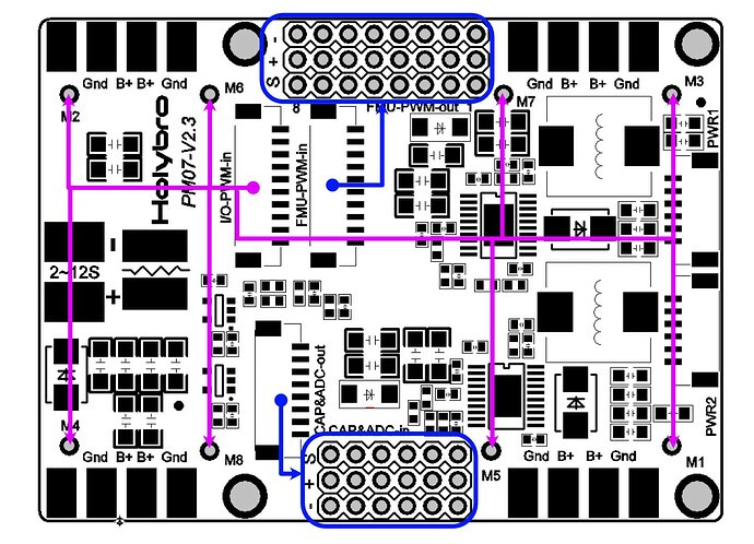 Pixhawk 4 PWM output connections diagram highlighting I/O PWM IN and FMU PWM OUT ports for servo motor control
Extensive research led to the discovery of a crucial detail: when utilizing I/O_PWM_IN from the Pixhawk 4, the purple connector outputs are the correct connections for Servos. The initial setup mistakenly had the servos connected to FMU-PWM-OUT.
Upon connecting a servo to the M1 output on the correct I/O_PWM_IN, servo functionality was finally achieved.
- M1 output produced signals corresponding to forward and backward movement on the left stick, with auto-centering, although the servos reacted with a noticeable delay.
- M3 output generated signals linked to left and right movement on the right stick, exhibiting very responsive servo movement directly mirroring stick input.
This difference in servo response speed and axis control raised questions. It appears M1 and M3 are configured to drive servos for hydro stats, indicating a specific pre-configuration.
Finally, progress was made in getting the servos to operate. The next step is to identify and test the throttle output to achieve full control. This experience underscores the importance of verifying the correct PWM output ports for servo connections on Pixhawk 4 to avoid control issues and ensure proper servo motor operation.