
Are you fascinated by gearmotors but deterred by their high cost for small projects? What if you could create your own miniature gearmotor from an incredibly affordable and readily available component? It turns out that cheap, mass-produced servo motors, often used in radio-controlled models and robotics, can be ingeniously modified into continuous rotation gearmotors. This hack transforms a standard servo into a miniature powerhouse, perfect for projects requiring controlled rotational movement at a fraction of the cost of dedicated gearmotors.
Modifying servos for continuous rotation is a well-known technique within the maker and hobbyist communities. A quick online search will reveal numerous tutorials and examples of this clever repurposing. While you can purchase pre-modified continuous rotation servos, such as those offered by Parallax, the real fun and cost-effectiveness lie in converting a standard micro servo yourself. For this project, we’ll be focusing on ultra-affordable micro servos like the Hextronic HXT500, often priced under $4. These Tiny Servo Motors are ideal candidates for this modification, giving you a miniature gearmotor that’s practically disposable, perfect for experimenting and learning.
This guide will walk you through the simple steps to transform a standard micro servo into a tiny, continuous rotation gearmotor. Let’s dive in and unlock the hidden potential of these miniature marvels.
Understanding Servo Modification for Continuous Rotation
To appreciate the modification, it’s helpful to understand how a standard servo motor operates. A servo motor is a self-contained unit that includes a DC motor, a gear train to increase torque and reduce speed, a potentiometer to sense the output shaft’s position, and sophisticated control electronics. Normally, a servo receives a pulse-width modulated (PWM) signal that dictates the desired angular position of its shaft. The internal electronics then compare this commanded position with the actual position reported by the potentiometer. Based on this comparison, the control circuitry adjusts the DC motor’s speed and direction to precisely move the shaft to the commanded angle and maintain that position.
The magic of the continuous rotation modification lies in effectively disabling the positional feedback loop. By removing the potentiometer from the control circuit and replacing it with two fixed resistors of equal value, we trick the servo’s electronics. The servo now no longer “knows” its shaft position. Instead, it interprets any input signal as a command to rotate continuously. The speed and direction of rotation are then controlled by how far the input pulse width deviates from the center point. Essentially, the servo now operates as a speed-controlled DC gearmotor, with the input signal determining the direction and speed rather than a specific angular position.
Step-by-Step Guide: Modifying Your Tiny Servo
Let’s get hands-on and transform our micro servo into a continuous rotation gearmotor. For this guide, we’ll use the Hextronic HXT500 servo, but the general principles apply to most micro servos.
Disassembling the Servo
The first step is to carefully disassemble the servo casing. These micro servos typically have a plastic housing composed of three snap-fit pieces. Using a small, flat-blade screwdriver or a similar thin, wedge-shaped tool, gently pry apart the plastic pieces. Start from the top and carefully remove the gears, noting their positions for potential reassembly if you ever want to revert the servo back to its original function. Once the top gears are removed, you can access the servo’s internal circuit board from the bottom of the casing.
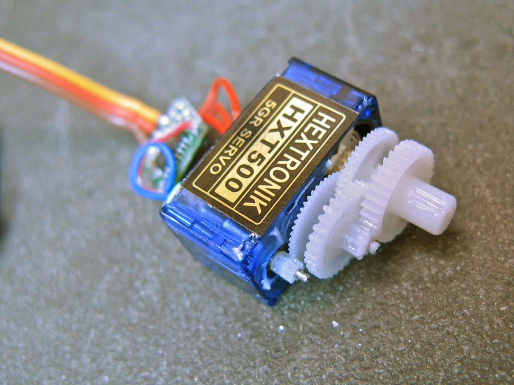 Disassembled servo showing gears and circuit board
Removing Mechanical Stops
Standard servos are designed for limited rotation and incorporate mechanical stops to prevent over-rotation. For continuous rotation, these stops need to be removed. On the HXT500 servo, there are typically two mechanical stops: a small metal tab at the base of the servo shaft and a plastic nub on the inside of the top casing. The metal tab can be easily bent back and forth using needle-nose pliers until it breaks off. The plastic nub on the top casing can be cleanly snipped off using diagonal cutters or a hobby knife. Ensure both stops are completely removed to allow for full 360-degree rotation.
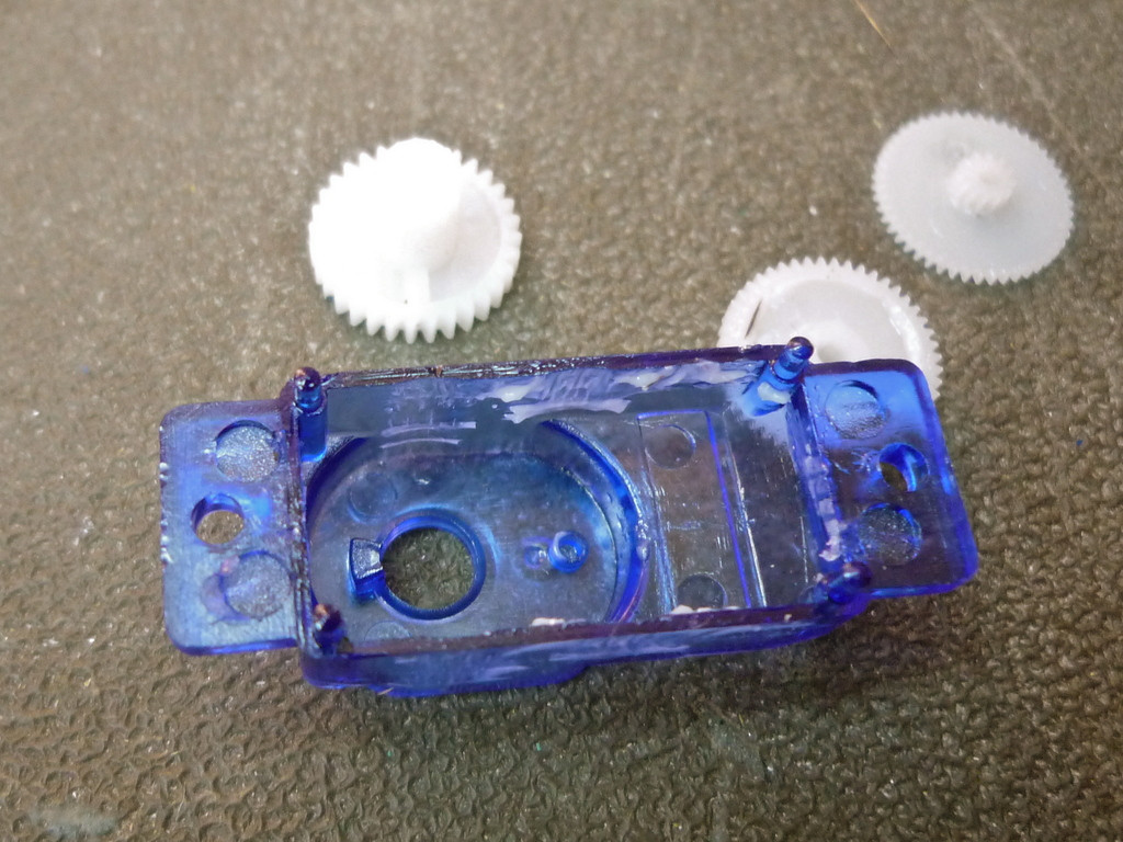 Plastic nub on servo casing removed
Replacing the Potentiometer with Resistors
The heart of the continuous rotation modification is replacing the potentiometer with fixed resistors. The potentiometer in the HXT500 servo is typically a 5k ohm potentiometer. We will replace it with two fixed resistors that sum to approximately 5k ohms. Two 2.2k ohm resistors or two 2.7k ohm resistors will work effectively.
Carefully unsolder the three wires connecting the potentiometer to the servo’s circuit board. Then, solder the two fixed resistors in series, and connect this resistor network to the three potentiometer solder pads on the circuit board. The center point of the resistor series should connect to the center pad on the board, and the two outer resistor ends can connect to the outer pads – the orientation usually doesn’t matter for the outer pads in this application, but if you are unsure, you can test and swap if needed. To insulate the new resistor assembly and prevent short circuits with the servo’s circuitry, wrap it with electrical tape or, ideally, slip a piece of heat-shrink tubing over it and shrink it with a heat gun or lighter. Carefully tuck the modified electronics back into the servo case and reassemble the servo.
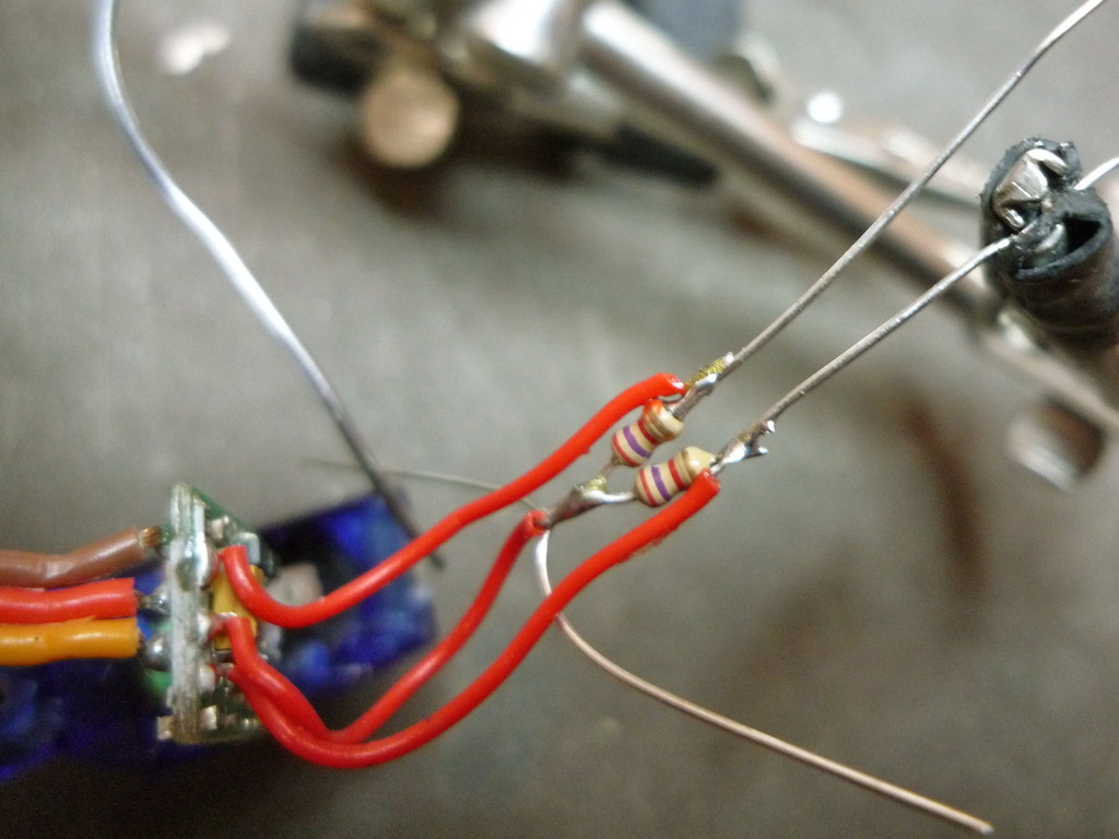 Potentiometer replaced with resistors and heat-shrink tubing
Integrating with Arduino and SoftwareServo Library
Now that you have your modified continuous rotation tiny servo motor, let’s explore how to control it using an Arduino microcontroller. The original article mentions the SoftwareServo library, which is a versatile option for controlling servos with Arduino, especially when you need to control multiple servos or use digital pins that aren’t dedicated PWM outputs. While the standard Servo library is excellent for position control servos, SoftwareServo provides the flexibility needed for continuous rotation modifications and other advanced servo control scenarios.
You can find the SoftwareServo library and example code online by searching for “Arduino SoftwareServo library.” The basic principle is to include the library in your Arduino sketch and then use the SoftwareServo object to control your modified servo. Instead of writing angles to the servo to control position, you will write angle values to control speed and direction. A value around 90 degrees typically represents the stop or neutral position. Values below 90 will command rotation in one direction, and values above 90 will command rotation in the opposite direction. The further you move from 90, the faster the servo will rotate.
#include <SoftwareServo.h>

SoftwareServo myServo;  // create servo object to control a servo

int potPin = A0;    // analog pin used to connect the potentiometer
int servoPin = 2;   // digital pin used to control the servo

void setup() {
  myServo.attach(servoPin);  // attaches the servo on pin 2 to the servo object
  Serial.begin(9600);
}

void loop() {
  int potValue = analogRead(potPin);            // reads the value of the potentiometer (0-1023)
  int servoSpeed = map(potValue, 0, 1023, 0, 180);  // scale it to use it with the servo (0-180)
  myServo.write(servoSpeed);                  // sets the servo speed according to the scaled value
  SoftwareServo::refresh();                       // call this at least every 20ms
  Serial.println(servoSpeed);
  delay(15);
}
This simple Arduino example code demonstrates controlling the speed and direction of your continuous rotation servo using a potentiometer. Connect a potentiometer to analog pin A0 and your modified servo to digital pin 2 (and appropriate power and ground connections – ensure your servo is adequately powered, often from a separate power supply rather than directly from the Arduino board). As you turn the potentiometer, the servo’s speed and direction will change.
Software Centering for Precision Control
One common observation after modifying a servo for continuous rotation is that a commanded angle of exactly 90 degrees might not perfectly stop the servo. This is because the two fixed resistors used to replace the potentiometer are rarely perfectly matched in value. This slight imbalance can cause a drift, where the servo creeps in one direction even when it should be stopped.
To compensate for this, the SoftwareServo library provides a handy function called setMaximumPulse(value). This function allows you to fine-tune the “center” or zero-speed point of your continuous rotation servo in software. To calibrate your servo, you’ll need to experiment with different maximumPulse values. Start with a value close to the default (2400) and incrementally adjust it while sending a command of 90 degrees to the servo. Observe if the servo is creeping forward or backward. If it is creeping, adjust the maximumPulse value up or down in small increments (e.g., 10 or 20) until you find a value where the servo stops completely when commanded to 90 degrees.
Once you find the optimal maximumPulse value for your specific servo, record it (perhaps write it on the servo itself for future reference). Then, in your Arduino setup() function, include the line myServo.setMaximumPulse(yourValue); to apply this calibration at the start of your program. This software centering ensures precise control and allows you to accurately stop the servo when needed.
Conclusion
By following these steps, you’ve successfully transformed a cheap tiny servo motor into a versatile continuous rotation gearmotor. This simple modification unlocks a world of possibilities for your DIY projects, robotics endeavors, and creative explorations. You now have access to a miniature, controllable motor at a fraction of the cost of dedicated gearmotors, perfect for adding motion to your next invention. Experiment with different control schemes, integrate it into your Arduino projects, and discover the power of these tiny, repurposed motors!