
Have you ever wondered about the technology that powers the precise movements of robotic arms in manufacturing, the accurate positioning of antennas tracking satellites, or the sophisticated control systems in automated machinery? The answer often lies in servo motors. These ingenious devices are essential for applications demanding accuracy and controlled motion.
Following our previous exploration of stepper motors in “What is a Stepper Motor and How it Works“, this article will delve into the world of servo motors. We will clarify what a servo motor is, how it operates, and explore its diverse types and applications. Let’s begin by establishing the fundamental aspects of servo motors.
Servo Motor Basics
At its core, a servo motor is a self-contained rotary actuator that allows for precise control of angular or linear position, velocity, and acceleration. Unlike standard electric motors that simply rotate continuously, servo motors are designed for controlled movement within a closed-loop feedback system. This system ensures that the motor accurately reaches and maintains a commanded position.
A servo motor system comprises several key components working in harmony:
- Servo Motor: The motor itself, responsible for generating motion.
- Control Circuit: The “brain” of the system, interpreting command signals and managing the motor’s operation.
- Position Feedback Sensor: Typically an encoder or resolver, this sensor provides real-time information about the motor shaft’s position and speed.
- Drive Gears (Optional): Gear systems can be integrated to adjust the motor’s torque and speed output.
- Amplifier: Boosts the control signal to provide sufficient power to drive the motor.
- Shaft: The output component of the motor, which rotates to perform the desired action.
- Potentiometer (in some simpler servos): Used for position feedback in basic servo systems.
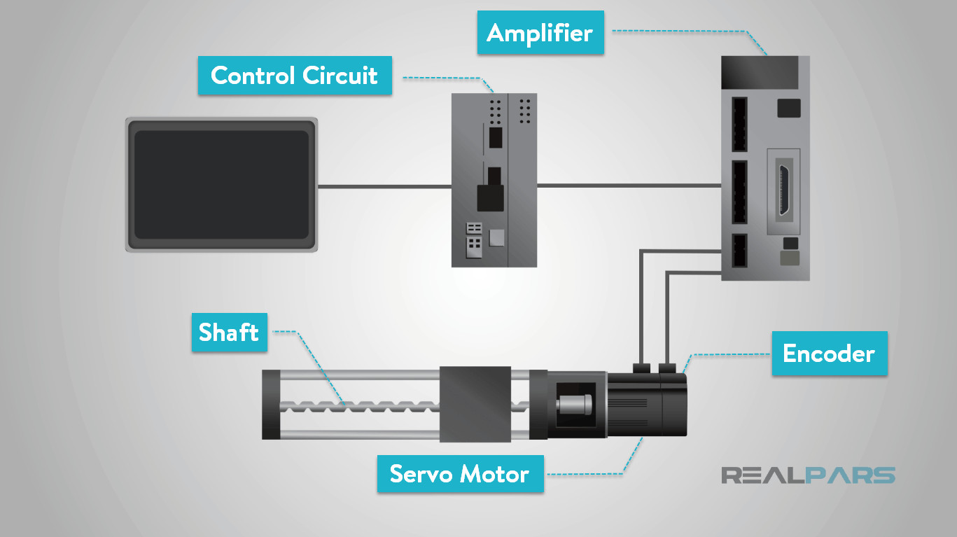 Components of a Servo Motor System for Precise Motion Control
The defining characteristic of a servo motor is its closed-loop control system. This mechanism continuously monitors the motor’s output and adjusts its operation to match the desired command. Imagine it as a highly skilled driver constantly correcting the steering wheel to stay on course.
 Servo Motor Feedback Mechanism for Position and Speed Regulation
The motor receives control commands in the form of electrical signals, either analog or digital. These signals dictate the desired position, speed, or torque. The control circuit then interprets this command and instructs the motor to move accordingly.
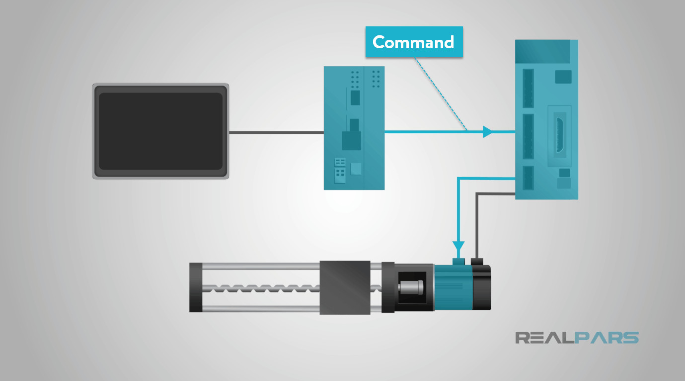 Servo Motor Control Command Input for Precise Movement
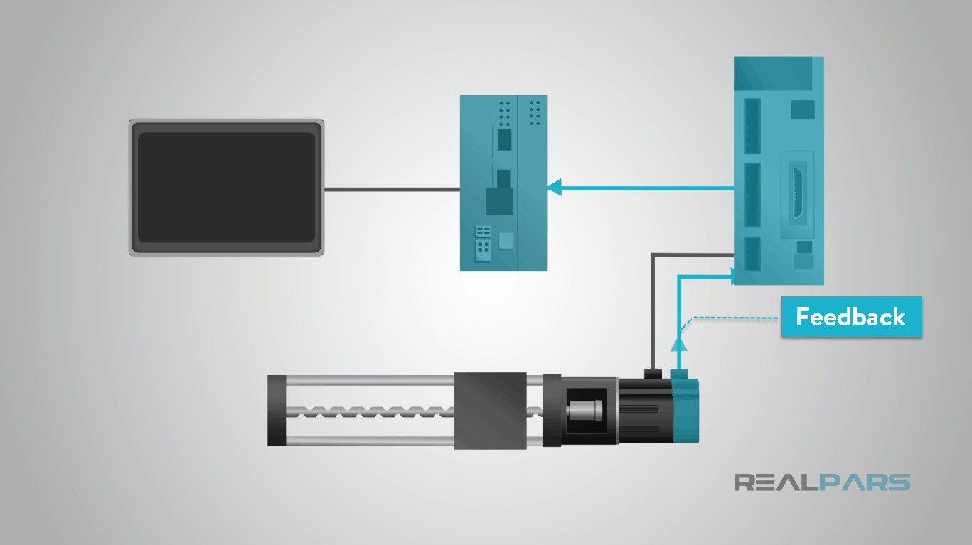
Crucially, the feedback sensor, often an encoder, continuously reports the actual position and speed of the motor shaft back to the control circuit. This feedback loop is essential for accuracy. The control circuit compares the desired position with the actual position from the encoder. If there’s a discrepancy, the control circuit adjusts the motor’s power to correct the error and ensure the shaft reaches the precise commanded position.
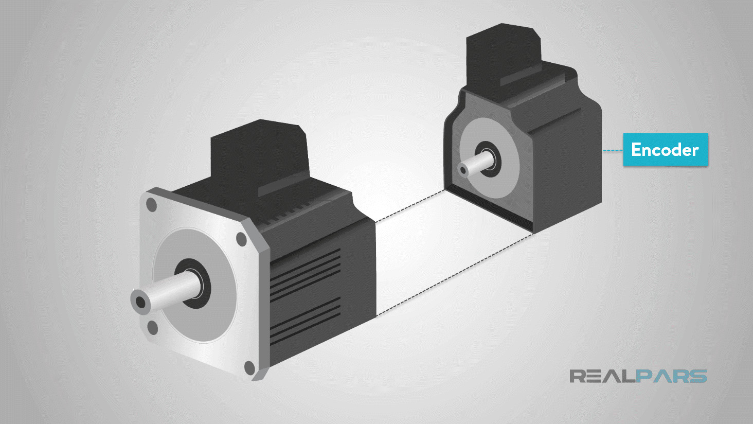 Servo Motor Encoder Providing Position and Speed Feedback for Closed-Loop Control
Types of Servo Motors
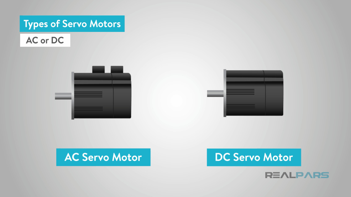
Servo motors can be categorized based on several factors, primarily their current type (AC or DC), commutation method (brushed or brushless), and rotor field type (synchronous or asynchronous). Understanding these classifications is key to selecting the right servo motor for a specific application.
The most fundamental distinction is between AC servo motors and DC servo motors, determined by the type of electrical current they utilize.
 Classification of Servo Motor Types Based on Current, Commutation, and Rotor Field
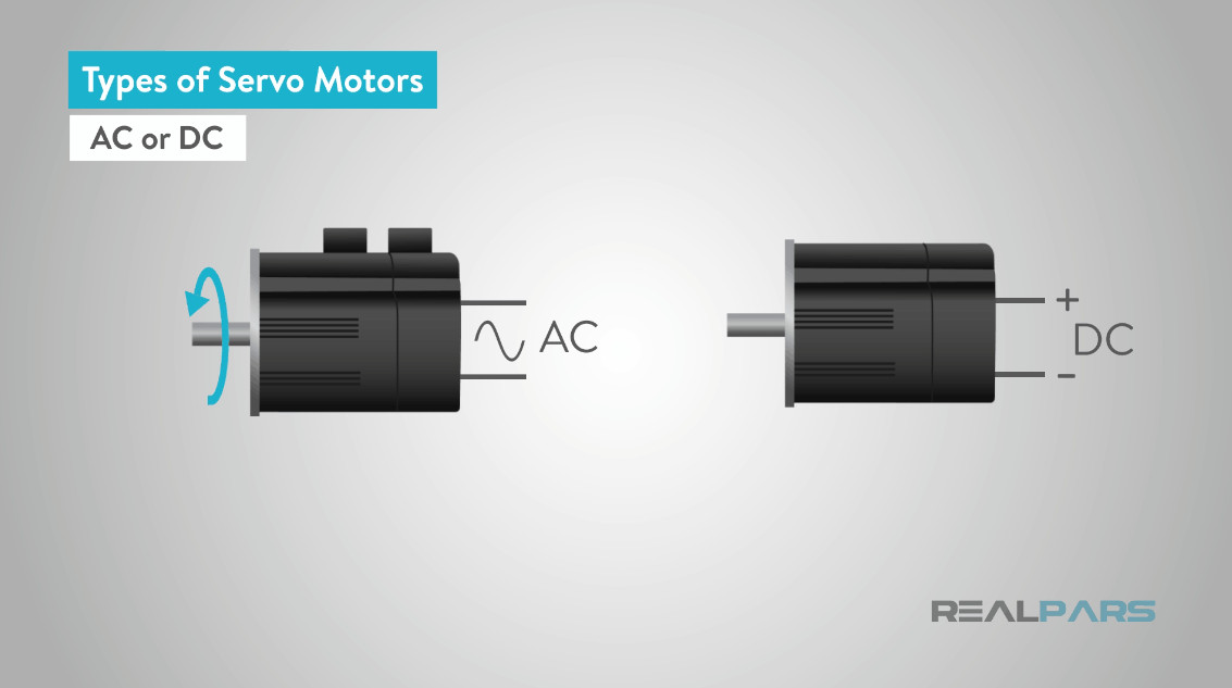
From a performance perspective, a key difference lies in speed control. DC motors exhibit a speed directly proportional to the applied voltage under a constant load. In contrast, the speed of an AC motor is dictated by the frequency of the voltage supply and the number of magnetic poles in its design.
 Speed Control Characteristics of AC and DC Servo Motors
While both AC and DC motors are employed in servo systems, AC servo motors generally excel in handling higher currents and are favored in demanding servo applications. These include robotics, automated production lines, and various industrial settings requiring high repetition rates and exceptional precision.
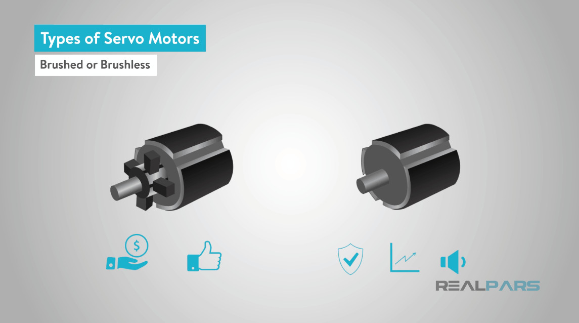
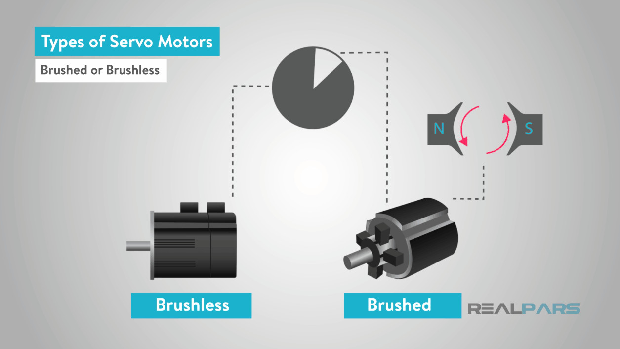
Another important categorization is whether a servo motor is brushed or brushless. This distinction primarily applies to DC servo motors. Brushed DC servo motors use mechanical brushes and a commutator for commutation, while brushless DC servo motors utilize electronic commutation.
 Brushed vs. Brushless Servo Motors: Commutation Methods and Advantages
A commutator is essentially a rotary switch that periodically reverses the current direction within the motor. It features metal contact segments on the rotor, against which “brushes” – typically made of carbon – press to maintain electrical contact as the rotor turns.
 Brushes and Commutator in a Brushed Servo Motor for Mechanical Commutation
Brushed servo motors are typically less expensive and simpler to control. However, brushless servo motors offer superior reliability, higher efficiency, and quieter operation due to the absence of mechanical wear associated with brushes. While AC motors are predominantly brushless, brushed permanent magnet DC motors are sometimes used as servo motors where simplicity and cost-effectiveness are priorities. The permanent magnet DC motor is a common type of brushed DC motor used in servo applications.
 Permanent Magnet DC Motor: A Common Brushed Servo Motor Type
Brushless DC motors replace the mechanical commutation system with electronic commutation. This is typically achieved using Hall effect sensors or encoders to track the rotor’s position and electronically switch the current flow in the motor windings.
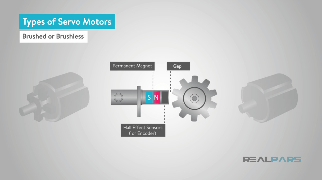 Hall Effect Sensors in a Brushless Servo Motor for Electronic Commutation
Although most AC motors are brushless, some designs like the universal motor, which can run on both AC and DC power, do incorporate brushes and mechanical commutation.
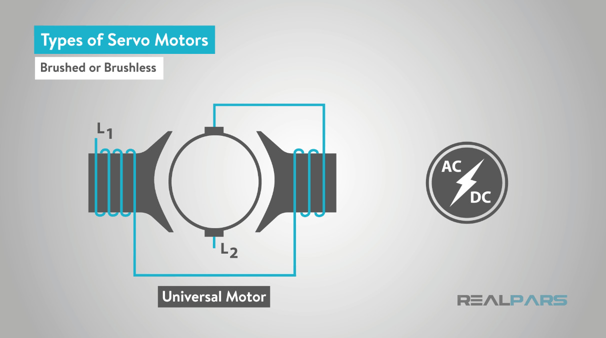 Universal Motors: An Example of Brushed AC Motors
Finally, servo motors are classified based on whether they utilize a synchronous or asynchronous rotating field, primarily relevant to AC servo motors.
In AC motors, speed is inherently linked to the frequency of the supply voltage and the number of magnetic poles. This theoretical maximum speed is known as the synchronous speed. In a synchronous servo motor, the rotor rotates precisely at this synchronous speed, maintaining perfect synchronization with the stator’s rotating magnetic field.
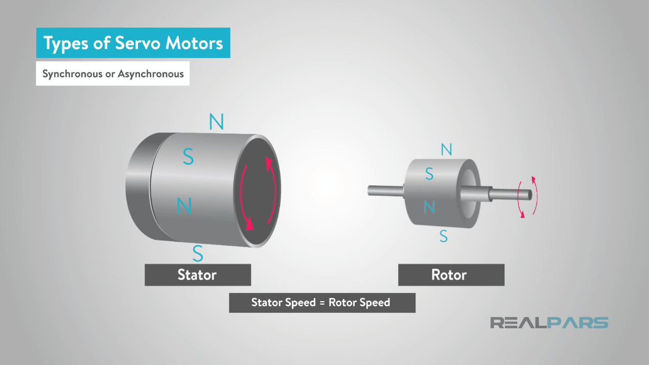 Synchronous vs. Asynchronous Servo Motors Based on Rotor Field Synchronization
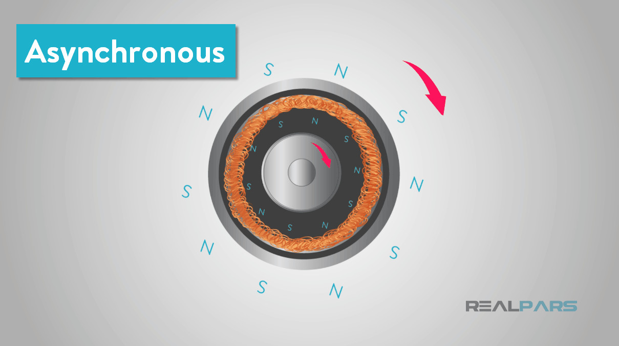
Conversely, an asynchronous servo motor, also known as an induction motor, operates with the rotor rotating slightly slower than the stator’s magnetic field. This “slip” is necessary for inducing current in the rotor. While typically less precise than synchronous motors in open-loop control, asynchronous servo motors can achieve precise control in closed-loop servo systems. The speed of asynchronous motors can be adjusted using various control techniques, such as changing the frequency of the supply voltage or altering the number of poles in the motor.
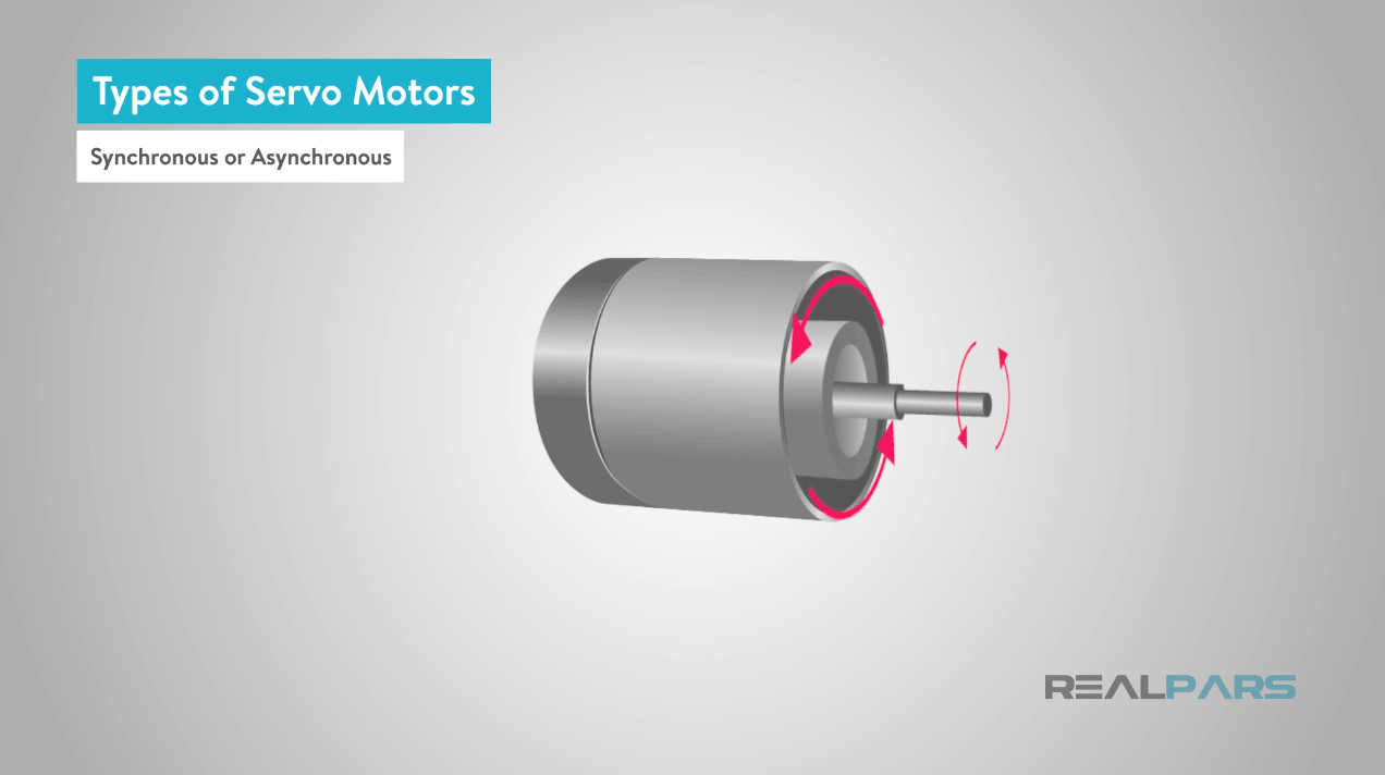 Asynchronous Motor: Rotor Speed Lags Behind Stator Field
Servo Motor Working Principles
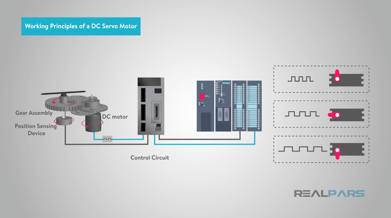
DC Servo Motor Working Principle:
The operation of a DC servo motor relies on the interaction of four main components: a DC motor, a position sensor, a gear assembly, and a control circuit.
The desired speed of a DC motor is directly proportional to the applied voltage. To control this speed, a potentiometer generates a voltage signal that serves as an input to an error amplifier. Alternatively, in some circuits, a control pulse is used to create a DC reference voltage, which is then converted by a pulse width voltage converter to determine the voltage applied to the error amplifier. For digital control systems, a PLC (Programmable Logic Controller) or other motion controllers can generate precise control pulses to achieve highly accurate motion control.
 DC Servo Motor Control Circuit Diagram Illustrating Feedback and Error Correction
The feedback sensor, typically a potentiometer linked to the motor shaft via gears, provides a voltage signal proportional to the shaft’s angular position. This feedback voltage is fed into the error comparator amplifier.
The amplifier compares the feedback voltage (representing the current position) with the desired position voltage. Any difference creates an error voltage, either positive or negative. This error voltage is then applied to the motor armature. The magnitude of the error voltage dictates the power supplied to the armature. The motor continues to rotate until the feedback voltage matches the desired voltage, at which point the error becomes zero, and the motor stops at the commanded position. If the error is negative, the armature voltage reverses, causing the motor to rotate in the opposite direction to correct the position.
AC Servo Motor Working Principle:
AC servo motors, both synchronous and asynchronous types, operate based on the interaction of stator and rotor magnetic fields.
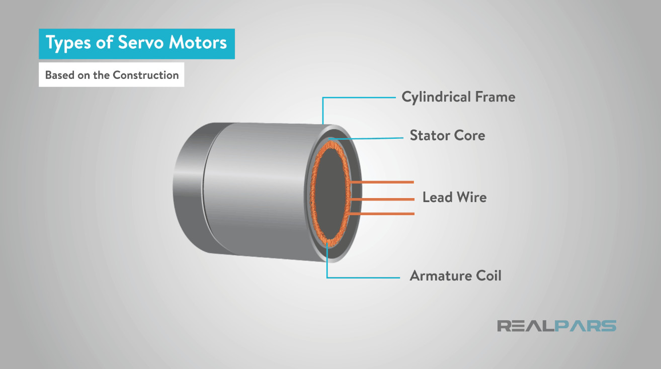
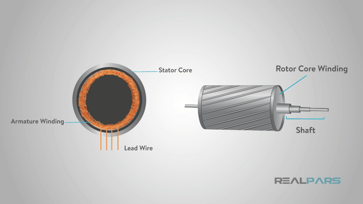
Synchronous AC Servo Motors: These consist of a stator and a rotor. The stator houses armature coils connected to the power supply. The rotor contains a permanent magnet.
 Synchronous AC Servo Motor Construction with Stator and Permanent Magnet Rotor
When the stator windings are energized, they create a rotating magnetic field. The rotor’s permanent magnet locks onto this rotating field and follows it synchronously – rotating at the same speed. Because the rotor is a permanent magnet, no rotor current is needed, contributing to higher motor efficiency. An encoder is usually attached to the rotor to provide precise position feedback to the servo controller.
Asynchronous (Induction) AC Servo Motors: The stator construction is similar to synchronous AC servos. However, the rotor in asynchronous motors typically features a squirrel cage or wound rotor.
 Induction Motor Rotor: Squirrel Cage Design
Only the stator winding receives AC power. This creates a rotating magnetic field (RMF) in the stator. As this RMF sweeps across the rotor conductors, it induces a current within them (Faraday’s law of induction), similar to a transformer. This induced rotor current, in turn, generates its own magnetic field, which interacts with the stator’s field, causing the rotor to rotate.
 Asynchronous Servo Motor Operating Principle: Induced Rotor Current and Rotation
The rotor in an asynchronous motor always rotates slightly slower than the stator’s magnetic field – hence the term “asynchronous.” This speed difference is necessary to induce current in the rotor.
Servo Motor Applications
Servo motors are ubiquitous in applications requiring precise and controlled motion. They are found in a wide range of industrial, commercial, and even consumer products.
In robotics, servo motors are fundamental, enabling precise movements at each joint of a robotic arm, allowing for complex and accurate tasks. Camera autofocus systems utilize miniature servo motors to adjust lens position with incredible precision, ensuring sharp images. Antenna positioning systems, such as those used by radio telescopes like the National Radio Astronomy Observatory, rely on servo motors to accurately control the azimuth and elevation axes for tracking celestial objects.
Beyond these examples, servo motors are essential in:
- CNC machinery: For precise control of cutting tools in milling machines, lathes, and bending machines.
- Automated manufacturing: In pick-and-place machines, packaging equipment, and assembly lines.
- Aerospace: In flight control surfaces, actuator systems, and precision positioning mechanisms.
- Medical equipment: In surgical robots, diagnostic equipment, and automated dispensing systems.
This concludes our exploration of servo motors. We hope this article has provided you with a clear understanding of what a servo motor is, how it works, its various types, and its widespread applications. With this knowledge, you are better equipped to delve into motion control projects and appreciate the technology behind precise movement in countless devices around us.
We at RealPars are dedicated to providing insightful educational content. We encourage you to explore more of our blogs for further learning and to deepen your understanding of automation and control systems. Stay tuned for more exciting topics!
With much enthusiasm,
The RealPars Team