
Have you ever wondered about the technology behind the smooth and precise movements of robotic arms in factories, the accurate positioning of antennas tracking satellites, or the sophisticated control systems in automated machinery? The answer often lies in servo motors. These ingenious devices are the unsung heroes of modern automation, providing the precise motion control necessary for a vast array of applications.
Expanding on our previous exploration of stepper motors, this article delves into the world of servo motors. We will explore what exactly a servo motor is, how it operates, its unique features, and the diverse applications where it excels. Understanding servo motors is crucial for anyone involved in motion control, robotics, automation, or industrial engineering.
Let’s begin our journey into the fascinating realm of servo motor technology.
Servo Motor Basics: Precision in Motion
At its core, a servo motor is a self-contained rotary actuator that allows for precise control over angular or linear position, velocity, and acceleration. Unlike standard motors that simply rotate continuously when powered, servo motors are designed for controlled and accurate movement, typically within a closed-loop feedback system.
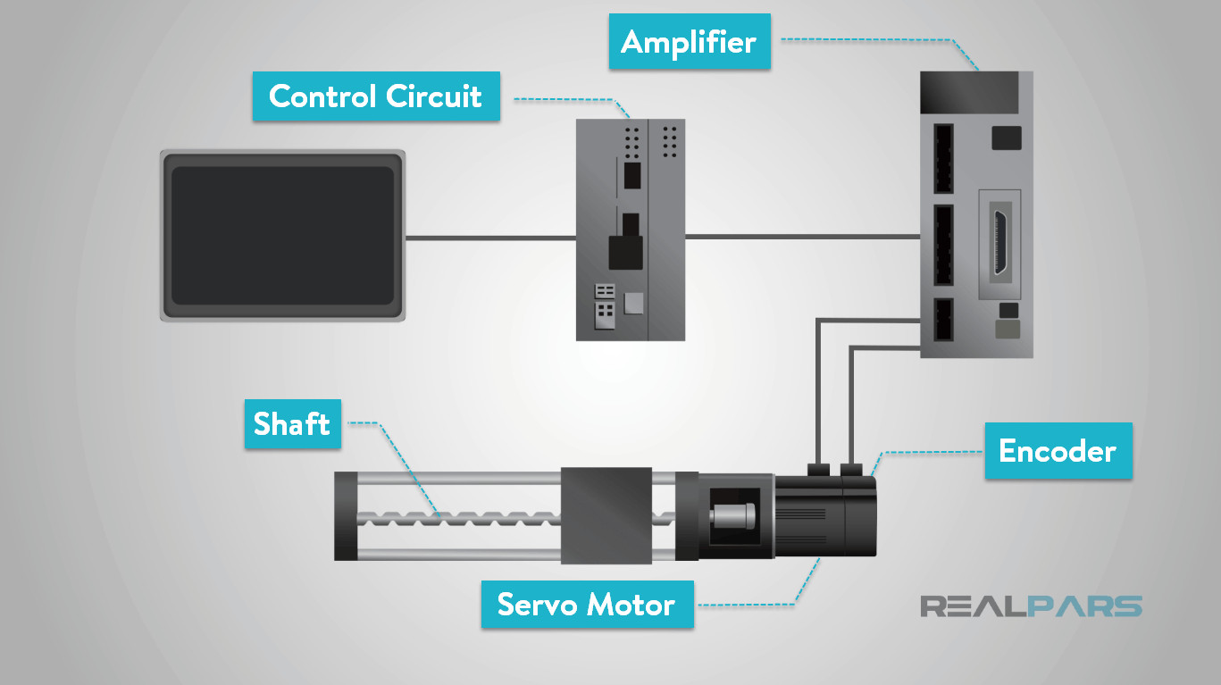
A servo motor system is comprised of several key components working in harmony:
- Servo Motor: The electric motor itself, responsible for generating the rotational force.
- Position Sensor (Encoder or Resolver): This crucial component provides feedback on the motor’s current position, speed, or both. Encoders typically use optical or magnetic sensors to track shaft rotation, while resolvers are electromechanical transducers.
- Control Circuit: The “brain” of the servo motor, this circuit receives command signals and processes feedback from the position sensor. It constantly adjusts the motor’s operation to achieve the desired position or motion.
- Drive Gears (Optional): Gear systems can be integrated to increase torque or reduce speed, tailoring the motor’s output to specific application needs.
- Amplifier: Boosts the control signal to provide sufficient power to drive the motor.
- Shaft: The output shaft of the motor that rotates and transmits motion to the connected mechanism.
- Potentiometer (Less Common in Modern Servos): In simpler, older servo designs, a potentiometer could be used for position feedback, though encoders and resolvers are now more prevalent due to their higher accuracy and reliability.
 Motion Control System
The defining characteristic of a servo motor is its closed-loop control system. This means the motor’s actual position is continuously monitored and compared to the desired position commanded by the controller. Any discrepancy, known as an error, is then corrected by the control circuit, ensuring the motor accurately reaches and maintains the commanded position. This feedback loop is what enables the exceptional precision of servo motors.
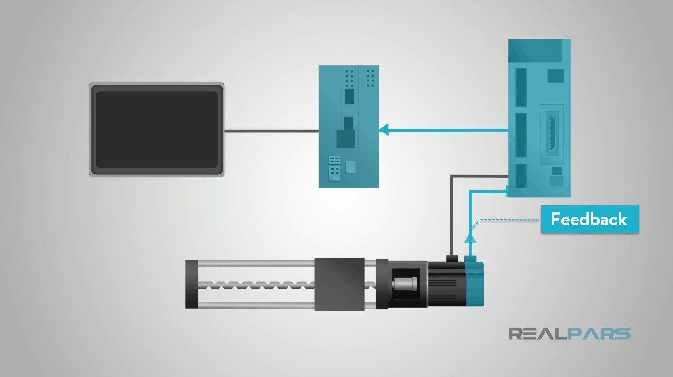 Servo Motor Feedback
Servo motors are controlled by electrical signals, which can be either analog or digital. These signals dictate the desired position, velocity, or torque. The control circuit interprets these signals and adjusts the power supplied to the motor to achieve the commanded motion.
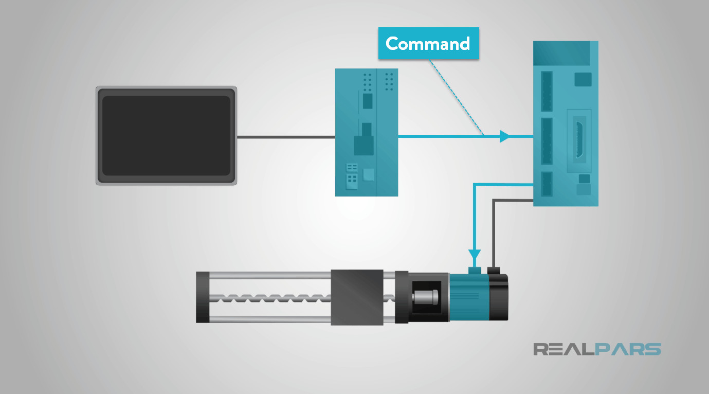 Servo Motor Control Command
Encoders or resolvers, acting as sensors, are typically integrated directly into the motor housing, often in conjunction with gear systems. These sensors provide real-time feedback on the motor’s position and speed, completing the closed-loop control and enabling highly accurate and responsive motion.
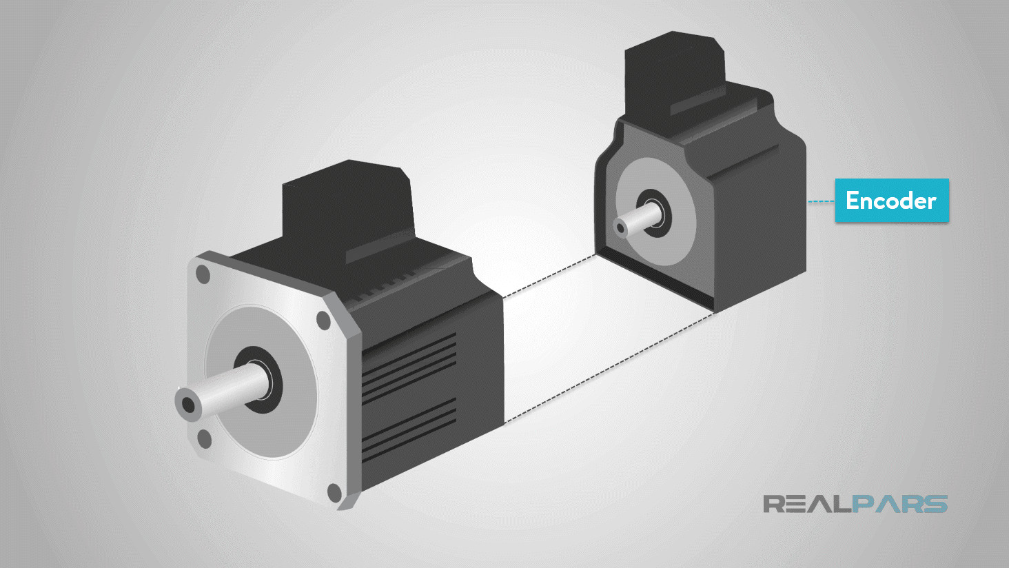 Servo Motor Encoder
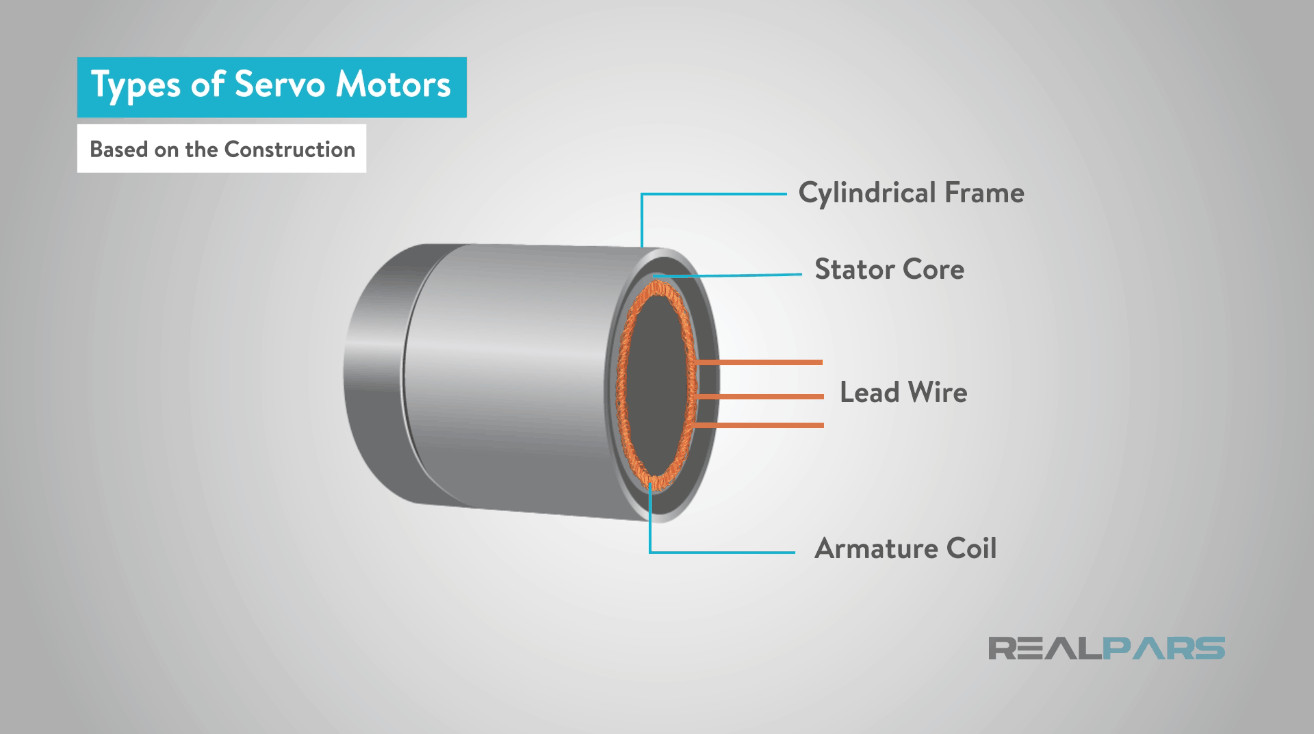
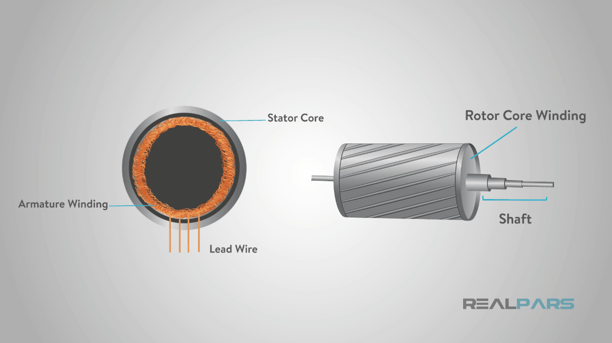
Types of Servo Motors: AC vs. DC and Beyond
Servo motors can be categorized based on several factors, primarily the type of current they use (AC or DC), the commutation method (brushed or brushless), and the nature of their rotating magnetic field (synchronous or asynchronous). Understanding these classifications is essential for selecting the right servo motor for a specific application.
AC vs. DC Servo Motors: Current Considerations
The most fundamental classification is based on the type of electrical current powering the motor: Alternating Current (AC) or Direct Current (DC).
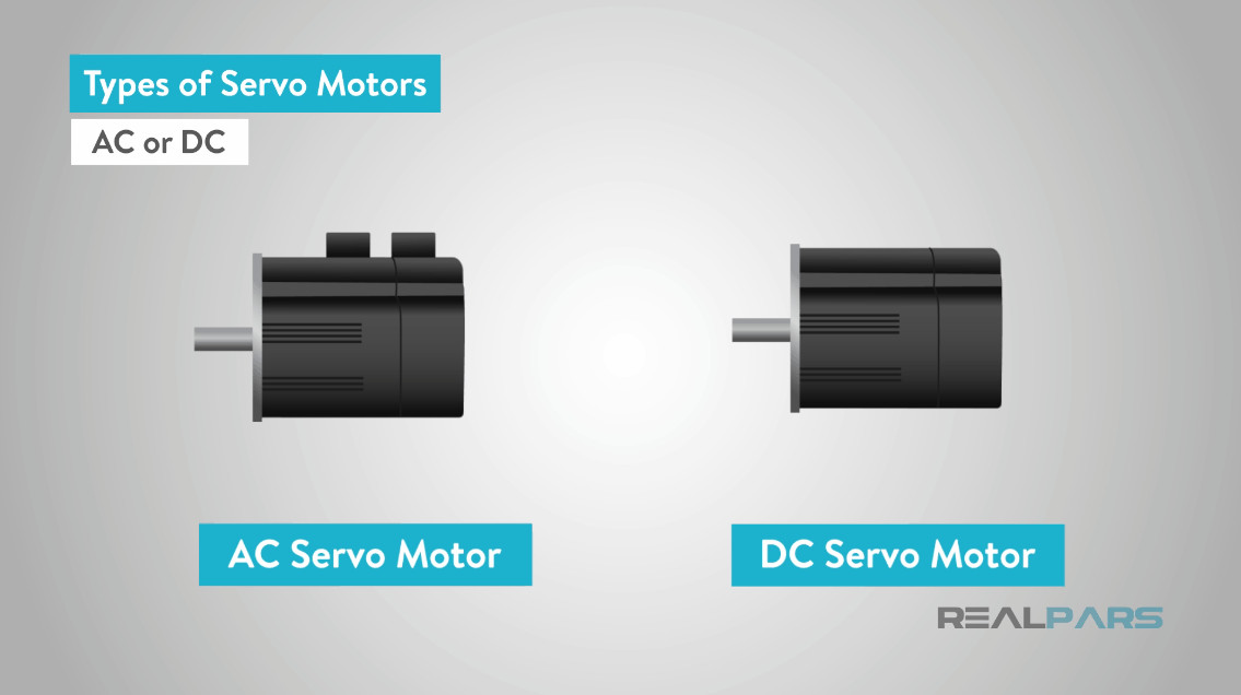 Types of Servo Motors
DC Servo Motors: In DC motors, speed is directly proportional to the applied voltage when the load is constant. This linear relationship makes speed control relatively straightforward.
AC Servo Motors: The speed of an AC motor is determined by the frequency of the applied voltage and the number of magnetic poles in the motor.
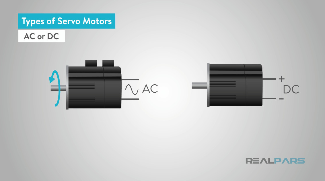 Servo Motor Speed
While both AC and DC motors find applications in servo systems, AC servo motors are generally favored in demanding industrial applications where higher current, greater durability, and high precision are paramount. Robotics, in-line manufacturing, and heavy-duty automation systems commonly utilize AC servo motors. DC servo motors may be preferred in lower-power applications or where simpler speed control is desired.
Brushed vs. Brushless Servo Motors: Commutation Methods
Another crucial distinction is between brushed and brushless servo motors, referring to the method of commutation – the process of switching current direction in the motor windings to maintain rotation.
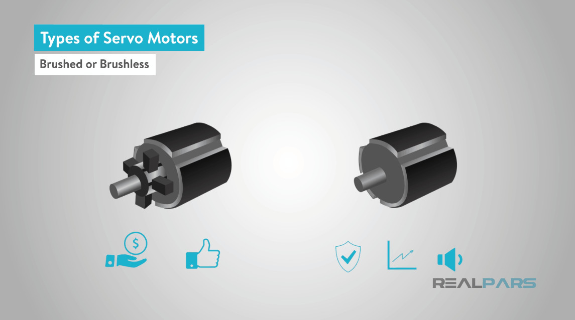 Brushed or brushless Servo Motors
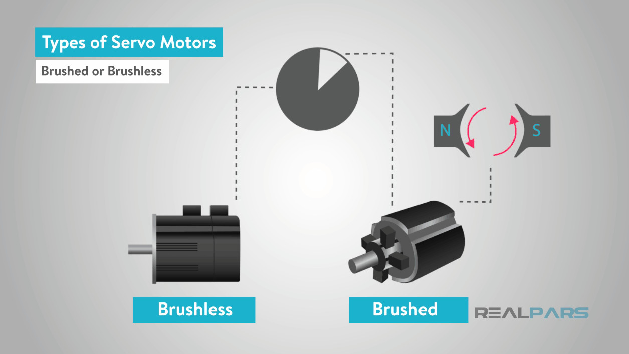
Brushed Servo Motors: These motors use physical brushes and a commutator for mechanical commutation. Brushes are conductive components that make contact with the rotating commutator, transferring current to the motor windings.
 Brushe in Servo Motors
Advantages of brushed motors: Simpler design, typically less expensive.
Disadvantages: Brushes wear out over time, requiring maintenance; lower efficiency due to friction; can generate electrical noise.
While less common in modern servo systems due to the rise of brushless technology, brushed permanent magnet DC motors are still used in some servo applications where cost-effectiveness is a primary concern and performance demands are less stringent.
 permanent magnet DC motor
Brushless Servo Motors: Brushless DC (BLDC) motors replace the mechanical brushes and commutator with electronic commutation. This is typically achieved using Hall effect sensors or encoders to detect the rotor’s position and electronically switch the current in the windings.
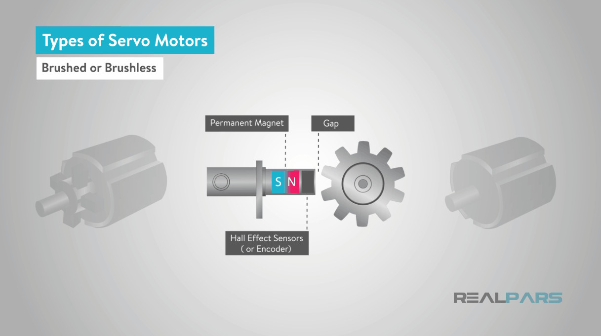 Hall effect sensors in Servo Motor
Advantages of brushless motors: Higher reliability (no brush wear), higher efficiency, less noise, longer lifespan, and generally better performance characteristics.
Disadvantages: More complex control circuitry, typically more expensive than brushed motors.
AC motors are predominantly brushless, although some AC motor designs, like universal motors (capable of running on both AC and DC), do utilize brushes and mechanical commutation.
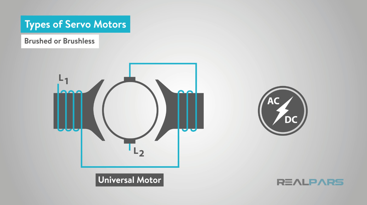 Universal Motors
Synchronous vs. Asynchronous Servo Motors: Rotating Field
The final classification considers the relationship between the rotor’s rotation speed and the stator’s rotating magnetic field in AC servo motors: synchronous or asynchronous.
 Synchronous or Asynchronous Srvo Motors
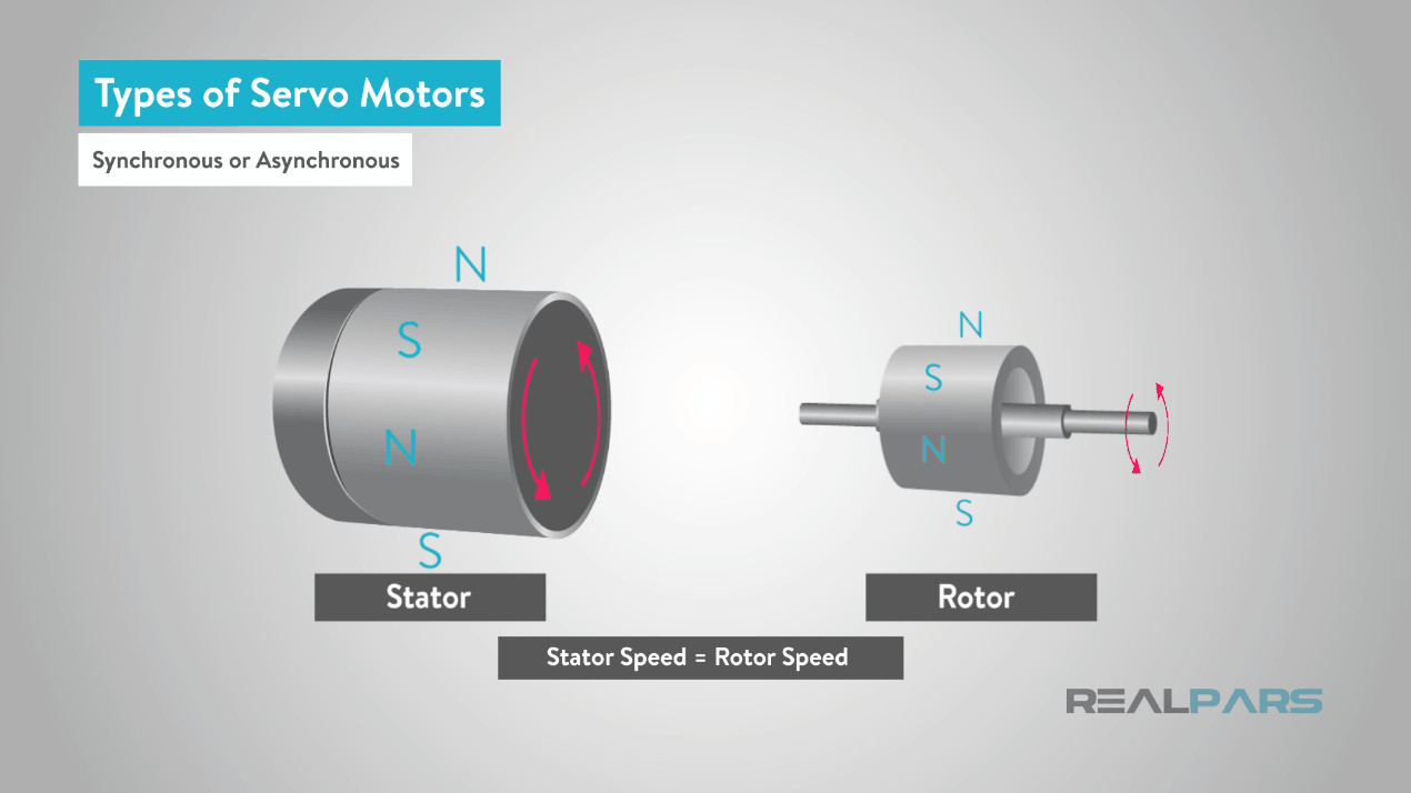
Synchronous Servo Motors: In synchronous AC servo motors, the rotor rotates at the same speed as the stator’s rotating magnetic field. This synchronous speed is directly determined by the frequency of the AC supply and the number of magnetic poles. These motors often utilize permanent magnets in the rotor. When the stator field is energized, the rotor locks into synchronism and follows the rotating field precisely. This characteristic contributes to their high precision and efficiency.
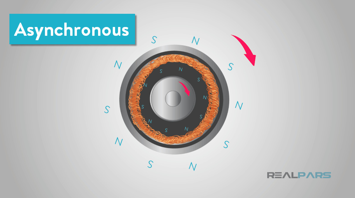
Asynchronous Servo Motors (Induction Servo Motors): Also known as induction servo motors, these motors operate with the rotor rotating at a speed slightly slower than the stator’s rotating magnetic field. The rotating magnetic field from the stator induces a current in the rotor windings (typically a squirrel cage rotor). This induced current creates its own magnetic field, which interacts with the stator field to produce torque and rotation. The speed difference between the stator field and rotor is known as “slip,” which is necessary for torque production.
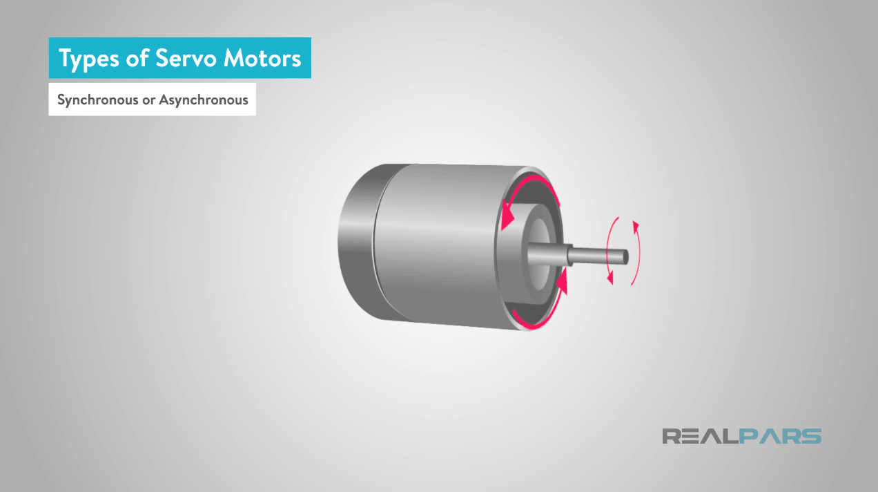 asynchronous motor
While traditionally less common in high-precision servo applications compared to synchronous motors, advancements in control technology have enabled asynchronous servo motors to achieve excellent performance in various servo systems, particularly where robustness and lower cost are important factors. Speed control in asynchronous motors can be achieved through methods like variable frequency drives (VFDs) that adjust the frequency of the power supply.
Working Principles: How Servo Motors Achieve Precision
The working principles of servo motors involve a combination of electrical motor operation and feedback control. Let’s examine the principles for both DC and AC servo motors.
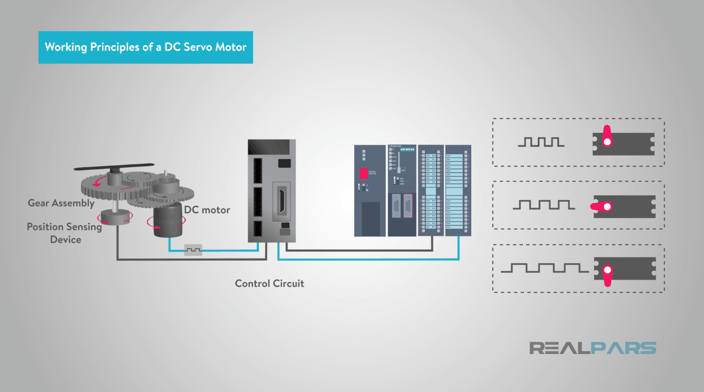
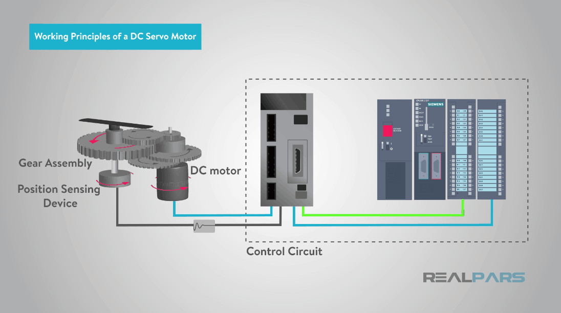
DC Servo Motor Working Principle
DC servo motors typically employ a closed-loop feedback system to precisely control position and speed. The key components working together are:
- DC Motor: The core of the system, its speed is controlled by the applied voltage.
- Position Sensing Device (Potentiometer or Encoder): Provides feedback on the motor shaft’s angular position. In simpler systems, a potentiometer might be used, generating a voltage proportional to the shaft angle. More advanced systems use encoders for higher accuracy.
- Gear Assembly (Optional): May be used to modify torque and speed characteristics.
- Control Circuit (Error Amplifier and Controller): This circuit is crucial for closed-loop operation.
 Servo Motor Control Circuit
Operation:
- Desired Position Input: A command signal, often a voltage or pulse width modulated (PWM) signal, represents the desired position. In digital control systems, a PLC or motion controller generates these control pulses.
- Feedback Signal: The position sensor (e.g., potentiometer or encoder) provides a feedback voltage or signal proportional to the current motor shaft position.
- Error Detection: The control circuit compares the desired position signal with the feedback signal. Any difference creates an “error signal.”
- Error Amplification: An error amplifier amplifies this error signal. The magnitude and polarity of the error signal indicate the direction and magnitude of the correction needed.
- Motor Drive: The amplified error signal is applied to the motor armature. A larger error signal results in a higher voltage applied to the motor, causing it to rotate more quickly.
- Position Correction: The motor rotates in the direction that reduces the error. As the motor approaches the desired position, the error signal diminishes.
- Zero Error State: The motor stops rotating when the feedback signal matches the desired position signal, effectively reducing the error to zero (or a negligible value within the system’s tolerance).
This continuous feedback and correction loop ensures that the DC servo motor precisely tracks the commanded position.
AC Servo Motor Working Principles
AC servo motors, both synchronous and asynchronous, also rely on closed-loop control for precise motion.
 working principles of an AC servo motor
Synchronous AC Servo Motor Working Principle:
- Stator and Rotor: Consists of a stator (stationary part) with windings and a rotor (rotating part) typically with permanent magnets.
- Stator Excitation: When AC voltage is applied to the stator windings, it creates a rotating magnetic field.
- Synchronous Rotation: The permanent magnet rotor locks onto and rotates synchronously with the stator’s rotating magnetic field. The rotor speed is directly tied to the frequency of the AC supply.
- Encoder Feedback: An encoder is mounted on the rotor to provide precise position feedback to the servo controller.
- Closed-Loop Control: The servo controller compares the desired position with the encoder feedback and adjusts the stator current to maintain accurate position and motion.
 synchronous AC servo motor
Asynchronous (Induction) AC Servo Motor Working Principle:
- Stator and Rotor (Squirrel Cage): Features a stator with windings and a rotor, often a squirrel cage rotor, where current is induced electromagnetically.
- Rotating Magnetic Field: AC current in the stator windings creates a rotating magnetic field.
- Induced Rotor Current: This rotating magnetic field induces a current in the rotor conductors, according to Faraday’s law of induction.
- Torque Generation: The interaction between the stator’s rotating magnetic field and the rotor’s induced current generates torque, causing the rotor to rotate.
- Asynchronous Speed: The rotor rotates slightly slower than the stator’s magnetic field (asynchronously).
- Speed Control: Speed is typically controlled using variable frequency drives (VFDs) to adjust the frequency of the AC power supplied to the stator.
- Feedback Control: Encoders are used for position and speed feedback, enabling closed-loop servo control even with asynchronous operation.
 Induction Motor
 Asynchronous Servo Motor
Servo Motor Applications: Precision in Action
Servo motors are indispensable in applications demanding precise and controlled motion. Their versatility and accuracy make them suitable for a wide range of industries and systems.
- Robotics: Servo motors are fundamental in robotics, powering each joint and axis of robotic arms and manipulators. They enable robots to perform complex and repeatable movements with high precision in manufacturing, assembly, and various automated tasks.
- Camera Autofocus: The autofocus systems in cameras rely on miniature servo motors to precisely adjust the lens position for sharp image focus.
- Antenna Positioning Systems: Large antenna systems, such as those used in satellite communication and radio telescopes (like those at the National Radio Astronomy Observatory), employ servo motors to accurately control azimuth (horizontal) and elevation (vertical) positioning for precise signal tracking.
- Industrial Automation: Servo motors are widely used in industrial machinery, including metal cutting and forming machines (milling machines, lathes, bending machines), packaging equipment, CNC machines, and automated assembly lines. They provide the precise motion control needed for accurate and efficient manufacturing processes.
- Military and Aerospace: Applications range from bomb disposal robots requiring delicate and controlled movements to aircraft control surfaces and precision guidance systems.
This exploration of servo motors provides a foundational understanding of their operation, types, and applications. Servo motors are essential components driving innovation and efficiency across numerous industries. As motion control technology continues to advance, servo motors will undoubtedly remain at the forefront, enabling increasingly sophisticated and precise automated systems.
We hope this guide has been informative and inspires you to delve deeper into the world of motion control. Stay tuned for more educational content from RealPars!
The RealPars Team.