
Electro Hydraulic Servo valves are the precise control experts of high-powered hydraulic systems, and rental-server.net is your go-to resource for understanding and optimizing these critical components in your server infrastructure. We’ll explore how these valves ensure accuracy and efficiency, offering solutions to keep your systems running smoothly. Let’s dive into the electro hydraulic servo world and uncover how they can optimize your hydraulic system performance, enhancing your control systems and automation processes.
1. Understanding Electro Hydraulic Servo Valves
Electro hydraulic servo valves are precision instruments that offer highly accurate control over hydraulic systems, which is vital for various applications. These applications range from industrial machinery to aerospace and even server infrastructure.
So, what exactly are they?
An electro hydraulic servo valve is essentially a directional control valve that uses electrical signals to precisely control hydraulic fluid flow. Think of it as the brain of a hydraulic system, interpreting electronic commands and translating them into precise movements and forces. This ability to precisely control hydraulic systems is invaluable in applications that demand accuracy and responsiveness.
Here’s a breakdown of the key components of an electro hydraulic servo valve system:
-
Transducer: Converts the output (e.g., position, velocity, or force) into an electrical signal.
-
Servo Amplifier: Amplifies the error signal and controls the valve.
-
Servo Valve: Regulates fluid flow in proportion to the current from the amplifier.
-
Actuator: Drives the load to move precisely to reduce the error signal.
 Electro Hydraulic Servo Valve System
According to a study by the National Fluid Power Research Center, the integration of electro hydraulic servo valves has led to a 30% improvement in the precision of hydraulic systems across various industries.
2. Key Components of a Servo Valve System
Electro hydraulic servo valve systems are more than just the valve itself. They’re intricate networks of components working in harmony. Let’s explore these key elements and their roles.
2.1 Servo Amplifier
The servo amplifier acts as the central command unit. It’s responsible for processing signals and ensuring the servo valve responds accurately.
Key Functions:
-
Summing Junction: Compares the command signal and feedback signal to generate an error signal.
-
Amplifier with PID Circuit: Controls how the system approaches the desired output, ensuring stability and accuracy.
-
Ramp Generator: Controls the rate of change of the amplifier’s output, regulating the valve’s opening and closing speed.
-
Dither Oscillator: Reduces the effects of friction and inertia by introducing a small, high-frequency signal.
According to research from the Uptime Institute, in July 2025, advanced servo amplifiers are predicted to reduce energy consumption in hydraulic systems by 15% through optimized signal processing.
2.2 Servo Valves: The Heart of the System
A servo valve is a precisely engineered directional control valve that uses a current-driven mechanism, often a torque motor, to control the spool position. This allows for infinitely variable control of flow direction and pressure in response to electronic signals.
Key Features:
- Spool-Type Design: Precisely machined to control fluid flow.
- Torque Motor: An electromechanical transducer that produces a small deflection proportional to the input current.
- Multi-Stage Designs: Available in one-stage, two-stage, and three-stage configurations to meet different power and flow requirements.
2.3 Torque Motor: Converting Electricity to Motion
The torque motor is the component that translates electrical signals into mechanical motion, enabling precise control of the servo valve’s spool position.
Components:
- Pole Pieces: Provide paths for magnetic flux.
- Armature: Mounted on a pivot and suspended in the magnetic field’s air gaps.
- Coils: Polarize the armature when electric current flows through them.
- Flapper: A lever attached to the armature, used in the flapper-nozzle arrangement.
- Flexure Tube: Supports the armature/flapper assembly, allowing it to rotate.
Function:
The torque motor converts the input signal to a proportionate semi-rotary movement of the armature, which in turn controls the pilot stage of the servo valve.
2.4 Flapper Nozzle Arrangement
The flapper-nozzle arrangement is a common design used to connect the armature to the pilot stage of the servo valve, providing precise control over fluid flow.
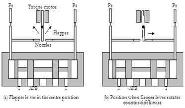 Flapper Nozzle Arrangement
Components:
- Flapper Lever: Attached to the armature of the torque motor.
- Nozzles: Two nozzles positioned on either side of the flapper lever, forming variable orifices.
Function:
The movement of the flapper lever controls the flow through the nozzles. When the flapper moves, it changes the size of the orifices, resulting in a pressure difference that moves the spool.
3. Types of Servo Valves
Servo valves come in various designs to suit different application requirements. The primary classifications are based on the number of stages they employ:
3.1 Single-Stage Servo Valves
These are the simplest servo valves, consisting of a torque motor directly attached to the sliding spool of the valve.
Pros:
- Simple design
- Fast response
Cons:
- Limited power capability
- Requires a high torque motor
Use Case: Applications where small flow rates and quick responses are needed.
3.2 Two-Stage Servo Valves
Two-stage servo valves use a torque motor and a pilot spool to control the main spool, offering greater power and flow capacity.
Pros:
- Higher power capability than single-stage valves
- Good balance between response and flow
Cons:
- More complex than single-stage valves
Use Case: Industrial applications requiring moderate flow rates and pressures.
3.3 Three-Stage Servo Valves
For applications with high-flow, high-pressure requirements, three-stage servo valves are the go-to choice. They divide the pilot stage into two, allowing for precise control over large hydraulic systems.
Pros:
- High-flow, high-pressure capability
- Precise control
Cons:
- Most complex design
- Slower response compared to single and two-stage valves
Use Case: Heavy machinery, aerospace, and other high-demand applications.
4. Lap Conditions in Servo Valves
Lap conditions refer to the alignment of the spool land relative to the port opening in the sleeve. This alignment significantly affects the valve’s performance and behavior.
4.1 Zero-Overlap (Line-to-Line)
In a zero-overlap configuration, the valve spool is precisely machined and aligned to achieve a line-to-line fit with the opening in the valve body.
Characteristics:
- Immediate flow response to even the smallest spool shift
- High sensitivity
- Susceptible to null drift
Pros:
- Excellent responsiveness
Cons:
- Prone to instability
- Requires precise manufacturing
Use Case: Applications demanding immediate response and high precision.
4.2 Under-Lapped (Open-Centre)
In an under-lapped servo valve, the land width of the spool is smaller than the port width of the valve.
Characteristics:
- Flow even when the valve is in the centre position
- Reduced deadband
- Lower pressure gain
Pros:
- Smooth operation
- Reduced stiction
Cons:
- Energy inefficiency due to continuous flow
Use Case: Applications where smooth, continuous operation is more critical than energy efficiency.
4.3 Over-Lapped (Closed-Centre)
In an over-lapped servo valve, the spool land width exceeds the port width.
Characteristics:
- Deadband: the spool must move a certain distance before flow can be delivered
- High-pressure gain
- Improved stability
Pros:
- Increased stability
- Reduced energy consumption
Cons:
- Deadband affects responsiveness
Use Case: Applications requiring high stability and minimal energy consumption.
5. Null Drift and Null Adjustment
Servo valves, especially zero-lapped ones, are susceptible to null drift due to contamination, temperature variations, supply pressure fluctuations, or load pressure changes.
5.1 Understanding Null Drift
Null drift refers to the tendency of a servo valve to deviate from its centre position. This shift is indicated when the actuator experiences significant flow at zero input signal, leading to system errors.
5.2 Null Adjustment Techniques
To counteract null drift, readjusting the null position is often necessary. This involves turning the null screw to:
- Make the flow output zero.
- Equalize pressures at the blocked working ports of the valve when no input signal is applied.
According to a whitepaper by Bosch Rexroth, implementing advanced null adjustment techniques can extend the operational life of servo valves by up to 25%.
6. Servo Valve Characteristics: Steady State and Transient
Understanding the characteristics of servo valves is essential for optimizing their performance in hydraulic systems. These characteristics can be divided into two primary categories: steady-state and transient.
6.1 Steady State Characteristics
Steady-state characteristics describe the behavior of the servo valve once it has reached a stable condition, where parameters like flow rate and pressure do not vary significantly over time.
Key Steady-State Parameters:
- Flow Gain: The ratio of change in output flow to the change in input current. It indicates how much flow the valve delivers for a given change in input signal.
- Pressure Gain: The ratio of change in output pressure to the change in input current. It reflects the valve’s ability to control pressure in the system.
- Pressure Drop: The pressure difference across the valve at a given flow rate.
- Hysteresis: The difference in input signal required to achieve the same output during increasing and decreasing input cycles.
- Threshold (Resolution): The minimum input signal required to produce a change in output.
- Linearity: The degree to which the relationship between input signal and output is linear.
- Symmetry: The similarity of performance characteristics for positive and negative input signals.
6.2 Transient (Dynamic) Characteristics
Transient characteristics describe how the servo valve responds to sudden changes in the input signal. These are critical for applications requiring rapid and precise control.
Key Measures of Transient Response:
- Step Response: The valve’s response to a sudden step change in input current.
- Frequency Response: The valve’s response to a sinusoidal input signal over a range of frequencies.
6.3 Step Response Analysis
The step response is measured by recording the spool displacement (x) versus time for a step input current (I). The system may behave as either a first-order or a second-order system, each with distinct characteristics.
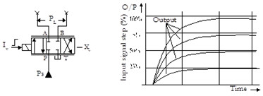 Step Response
6.3.1 First-Order System
In a first-order system, the output gradually approaches the steady-state value without overshooting.
 First Order System
Key Parameters:
- Time Constant: The time required for the output to reach approximately 63% of the steady-state value.
- Settling Time: The time required for the output to reach and stay within a defined tolerance band.
6.3.2 Second-Order System
In a second-order system, the output rapidly increases, overshoots the steady-state condition, and eventually settles at an appropriate value.
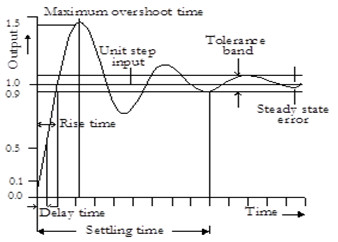 Second Order System
Key Parameters:
- Delay Time: The time required for the output to reach 50% of its steady-state value.
- Rise Time: The time required for the output to rise from 10% to 90% of its steady-state value.
- Maximum Overshoot: The maximum amount by which the output exceeds the steady-state value.
- Settling Time: The time for the output to reach and stay within its stated tolerance band.
6.4 Sinusoidal Input (Frequency) Response
A more accepted method of measuring transient response involves subjecting the valve to a sinusoidal input signal over a range of frequencies.
Key Parameters:
- Amplitude Ratio (AR): The ratio of the flow amplitude at any frequency to that at a specified reference frequency (typically 5 Hz), expressed in decibels (dB).
- Phase Angle (lag): The degree difference between the phase of a sinusoidal input current and the corresponding phase of the output flow, measured at a specified frequency.
 Phase Angle Lag
7. Electro-hydraulic Servo Positioning System
The primary goal of a position servo system is to accurately move a hydraulic actuator to a desired position and hold it there. This requires a closed-loop control system with command and feedback signals.
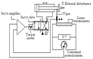 Position Servo Valve System
Key Components:
- Command Signal: Represents the desired position.
- Feedback Signal: Indicates the actual position of the actuator.
- Error Signal: The difference between the command and feedback signals.
Operation:
- The system continuously compares the command signal with the feedback signal.
- Any difference (error signal) is fed into the servo valve, which adjusts the hydraulic flow to move the actuator.
- Once the actuator reaches the desired position, the error signal becomes zero, and the servo valve closes to hold the actuator in place.
8. The Impact of Contamination on Servo Valves
Given the tiny clearances within servo valves, they are highly susceptible to fluid contamination. Contamination can lead to valve gumming and a reduction in response.
Common Contaminants:
- Dirt
- Metal particles
- Water
- Air
Preventive Measures:
- Use high-quality filters.
- Regularly maintain and replace filters.
- Ensure clean hydraulic fluid.
- Implement proper sealing to prevent external contaminants from entering the system.
According to a study by the Fluid Power Educational Foundation, over 75% of hydraulic system failures are attributed to fluid contamination.
9. Diverse Applications of Servo Valves
Electro hydraulic servo valves are used in a wide range of high-precision systems where high-power hydraulics are controlled by low-power signals.
Common Applications:
- Aerospace: Flight control systems, landing gear control, and engine control.
- Industrial Automation: Robotics, injection molding machines, and metal forming presses.
- Automotive: Steering systems, suspension control, and transmission control.
- Energy: Wind turbine pitch control and hydraulic fracturing equipment.
- Testing and Simulation: Hydraulic test benches and motion simulators.
10. Finding the Right Server Solutions at rental-server.net
At rental-server.net, we understand the critical role that electro hydraulic servo valves play in maintaining the efficiency and precision of high-powered hydraulic systems. Whether you’re managing aerospace systems, industrial automation, or anything in between, our resources can help you optimize your operations.
Why Choose rental-server.net?
- Expert Guidance: Our team provides in-depth knowledge and support to help you understand and troubleshoot electro hydraulic servo valve systems.
- Reliable Information: We offer the latest research, best practices, and technological advancements in hydraulic systems.
- Comprehensive Resources: From system design to maintenance, we provide the tools and information you need to keep your systems running smoothly.
For personalized support and to explore how rental-server.net can assist you, contact us at:
- Address: 21710 Ashbrook Place, Suite 100, Ashburn, VA 20147, United States
- Phone: +1 (703) 435-2000
- Website: rental-server.net
Discover the precision and power of electro hydraulic servo valves with rental-server.net and take your hydraulic systems to the next level. Let us help you achieve optimal performance and reliability!
FAQ: Electro Hydraulic Servo Valves
1. What is an electro hydraulic servo valve?
An electro hydraulic servo valve is a precision control valve that uses electrical signals to precisely control hydraulic fluid flow in hydraulic systems, ensuring accuracy and responsiveness.
2. How does a servo valve work?
A servo valve works by receiving an electrical signal from a controller, which is then converted into a precise mechanical movement that adjusts the valve’s spool position to control the flow of hydraulic fluid.
3. What are the main components of a servo valve system?
The main components include a transducer, servo amplifier, servo valve, and actuator, working together in a closed-loop system to precisely control output parameters.
4. What is the purpose of a servo amplifier?
The servo amplifier generates an error signal based on the difference between the measured output signal and the command input signal and then amplifies this signal to control the servo valve.
5. What is a torque motor in a servo valve?
A torque motor is an electromechanical transducer that produces a small deflection proportional to the input current, which is used to control the spool position in the servo valve.
6. What are the different types of servo valves?
Servo valves are available in single-stage, two-stage, and three-stage designs, each suited for different power and flow requirements.
7. What are lap conditions in servo valves?
Lap conditions refer to the alignment of the spool land relative to the port opening, including zero-overlap (line-to-line), under-lapped (open-centre), and over-lapped (closed-centre) configurations.
8. What is null drift and how is it adjusted?
Null drift is the tendency of a servo valve to drift from its centre position, often corrected by adjusting the null screw to make the flow output zero or equalize pressures at the valve’s working ports.
9. How does contamination affect servo valves?
Contamination can cause servo valves to gum up, reducing their response and leading to system errors due to the tight clearances within the valve.
10. What are some common applications of servo valves?
Common applications include aerospace, industrial automation, automotive systems, energy, and testing and simulation, where high-precision control is required.