
Setting up a dedicated workspace can significantly enhance the efficiency and enjoyment of electronics projects. For many hobbyists, a simple folding table can serve as an initial workbench, providing a space to keep projects in progress without constant setup and teardown. While materials like plastic might raise concerns about static buildup, careful grounding practices can mitigate these issues, allowing for focused work on projects like servo control.
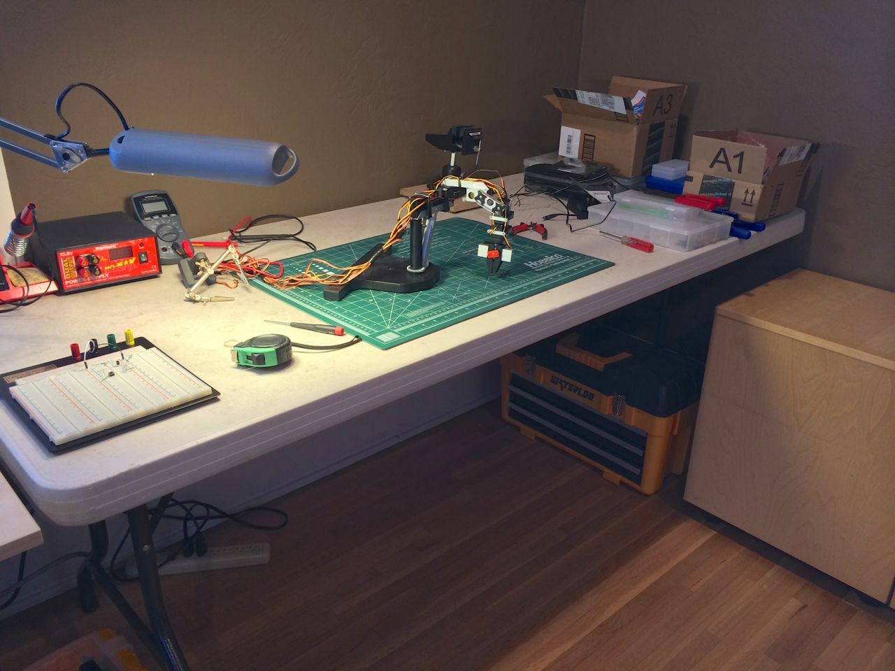 Workspace setup with a folding table and electronic components, illustrating a DIY electronics project environment for servo control experiments.
One common application in DIY electronics is controlling servo motors. Servos are essential components in robotics and automation, known for their precision in angular movement. If you’re exploring servo control, you might wonder: Do You Use 555 Timers For Servos? The answer is yes, and it’s a valuable learning experience, especially for understanding the fundamentals of servo operation and pulse width modulation (PWM).
Understanding Servo Control Signals
Servos operate using a pulse width modulation (PWM) signal. They typically have three wires: ground, power, and signal. The signal wire is where the control happens. To position a servo, you need to send it a pulse of a specific duration at regular intervals, typically every 20 milliseconds (50Hz).
The position of the servo arm is determined by the width of this pulse. A pulse width of 1.5 milliseconds usually corresponds to the servo’s neutral or 90-degree position. A shorter pulse, around 1 millisecond, moves the servo towards 0 degrees, and a longer pulse, around 2 milliseconds, moves it towards 180 degrees. While the 50Hz frequency is generally suitable, the precise frequency isn’t as critical as the pulse width for standard servos.
The 555 Timer as a Servo Controller
The 555 timer IC is a versatile chip that can be configured in various modes, including astable mode, which generates a continuous series of pulses. This makes it suitable for creating the PWM signal needed for servo control. By carefully selecting resistors and capacitors in a 555 astable circuit, you can adjust the pulse width and frequency to control a servo motor.
Building a servo controller with a 555 timer is a hands-on way to understand how servos are driven. It involves designing a circuit that outputs the correct pulse widths and frequencies.
Circuit Design and Considerations
A basic 555 servo controller circuit involves connecting the 555 timer in astable mode. A potentiometer is often incorporated into the circuit to allow for variable pulse width adjustment, giving you manual control over the servo position.
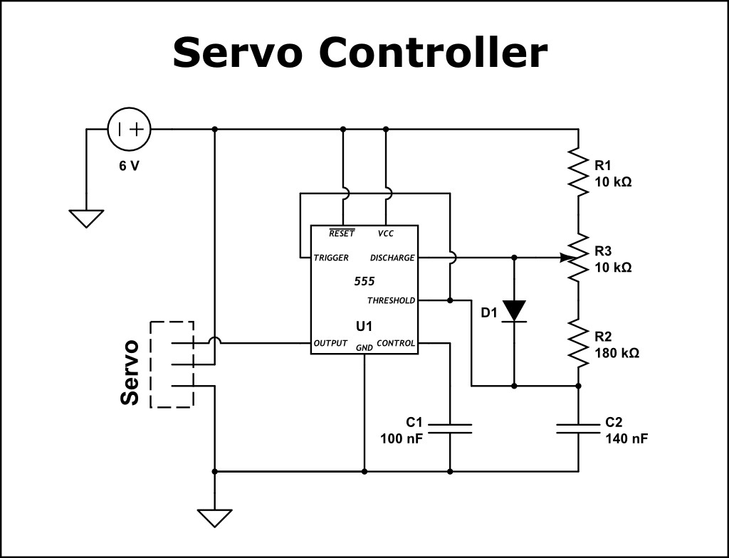 Schematic diagram of a 555 timer circuit designed for servo motor control, demonstrating a classic electronic circuit for generating PWM signals.
When designing such a circuit, component selection is crucial. Resistor and capacitor values determine the frequency and pulse width. Calculations, potentially aided by spreadsheets, are necessary to find component combinations that produce the desired servo control range. Tools like oscilloscopes, while not essential for basic operation, can be incredibly helpful for visualizing the output waveform and fine-tuning the circuit.
Challenges and Learning
Building a 555 servo controller is not without its challenges, especially for beginners. Common hurdles include:
- Circuit Design Errors: Mistakes in wiring and component placement are common but are valuable learning opportunities.
- Component Availability: Sometimes, you might find yourself missing specific resistor values or needing to work with components you have on hand, requiring creative problem-solving.
- Troubleshooting: Without tools like oscilloscopes, diagnosing issues can be more complex, requiring a deeper understanding of the 555 timer’s operation.
Overcoming these challenges significantly enhances your understanding of electronics and circuit design. Successfully building a working servo controller from scratch with a 555 timer provides a strong sense of accomplishment and a deeper grasp of waveform generation.
Alternatives and Modern Approaches
While 555 timers can effectively control servos, modern microcontroller platforms like Arduino offer simpler and more versatile solutions. Arduino servo shields, for example, are readily available and provide dedicated pins and libraries for easy servo control, often preferred in contemporary projects for their ease of use and programmability for more complex servo movements.
Conclusion
Using a 555 timer to control servos is a feasible and educational project, particularly for those looking to delve into the fundamentals of electronics and PWM. It provides a hands-on understanding of servo operation and circuit design principles. While more streamlined methods exist with microcontrollers and dedicated shields, the experience of building a 555 servo controller remains a valuable stepping stone in electronics learning, answering the question: yes, you can use 555 timers for servos, and doing so offers significant educational benefits.